It was a tough hardware day today. I’m taking tomorrow off from this bullshit.
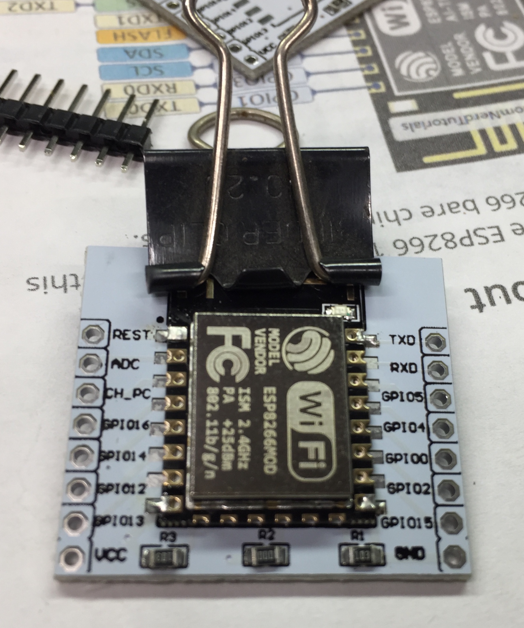
My 915Mhz RFM95 LoRa modules arrived! I’d seen I could use my ESP12 breakout board to get breadboard compatible pins so I soldered the RFM95 to those and also soldered up two more ESP12s. I’m going to try and follow this LoRa ESP8266 & Radio RFM95 tutorial.
I used a binder clip to hold the ESP module in place while I did the first solder joints.
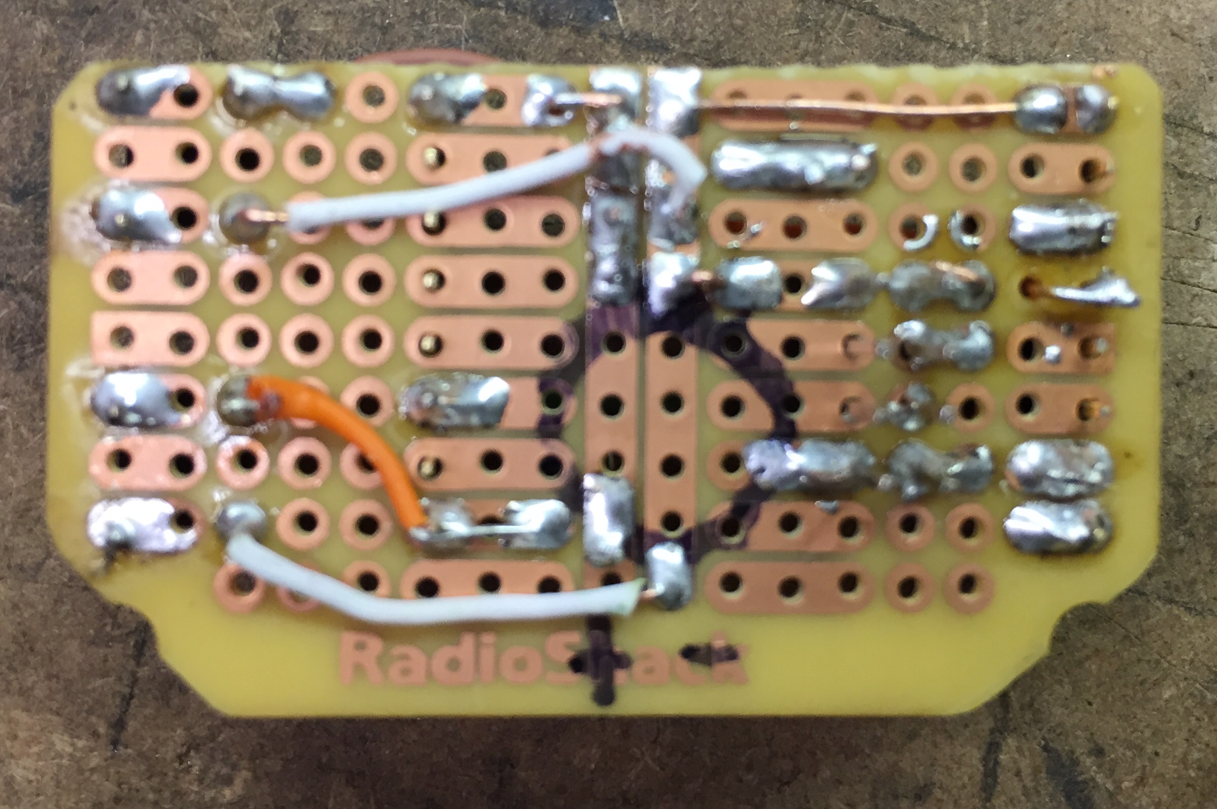
But first those ESP12s needed flashing and I was going to setup a breadboard like this to do it, but figured I’m going to do a lot of this in the future so why not make something reusable. I followed the schematic on that breadboard page and soldered something up.
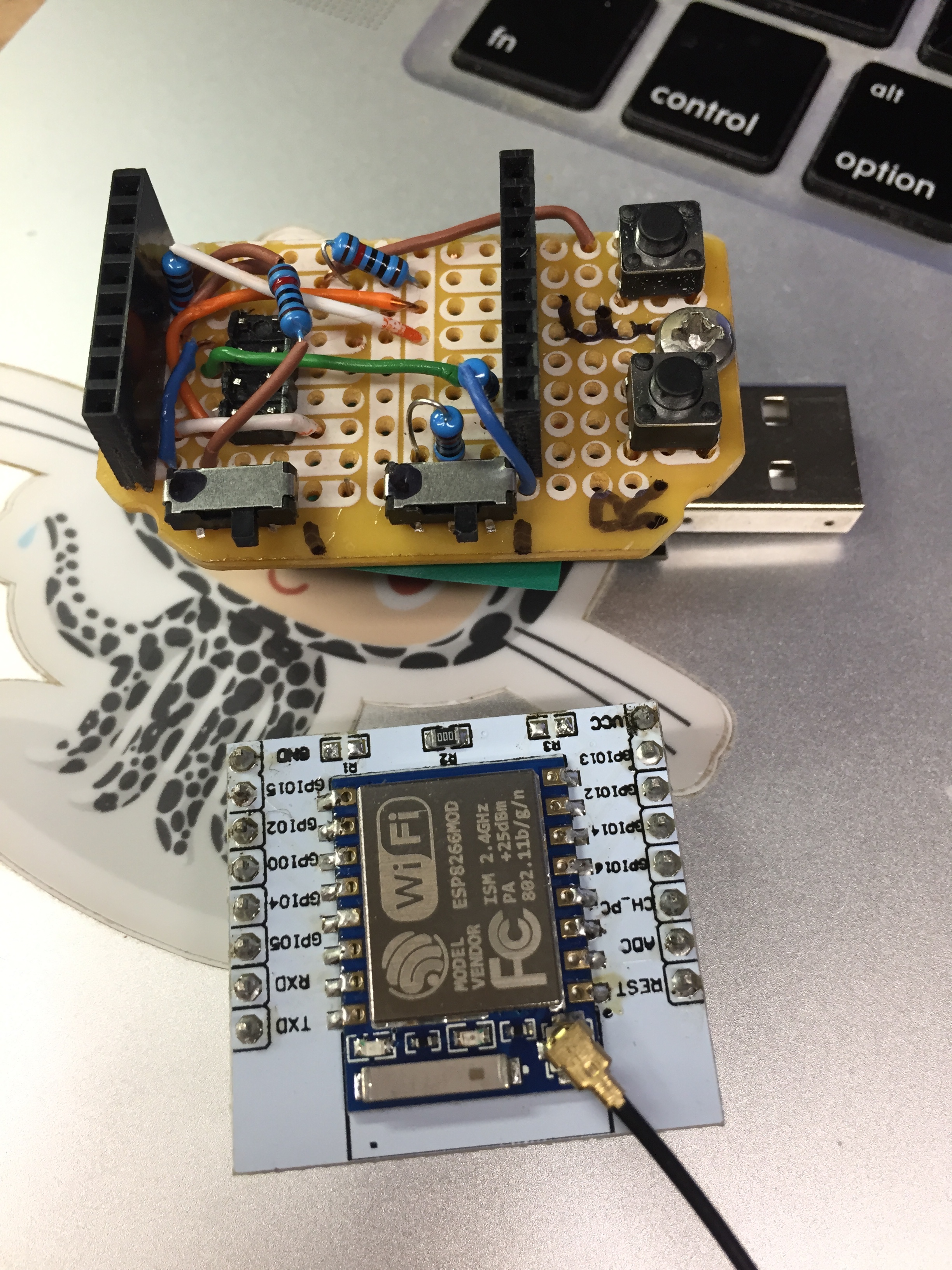
Here’s v1.
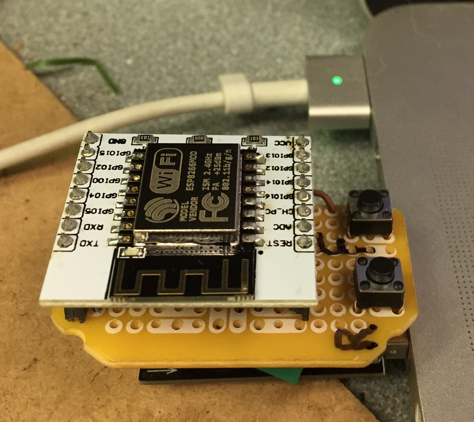
As you can see it plugs into the top of my ESP01 USB adapter.
It’s not pretty but it works. The reset and flash buttons are super handy.
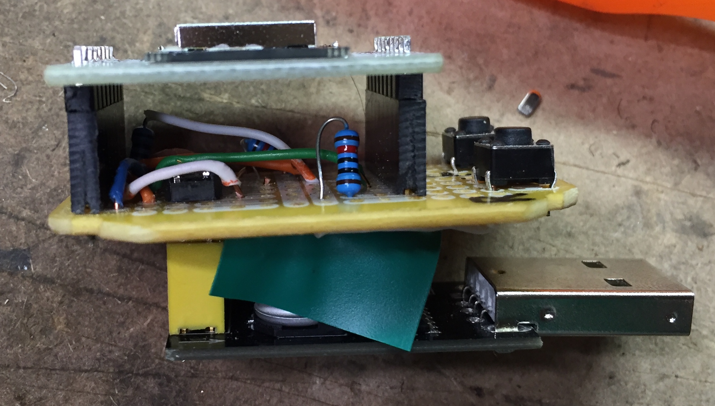
The sharpie cricle marks where the capacitor on the ESP01 USB serial board is. I put electrical tape over it to make it not short everything out.
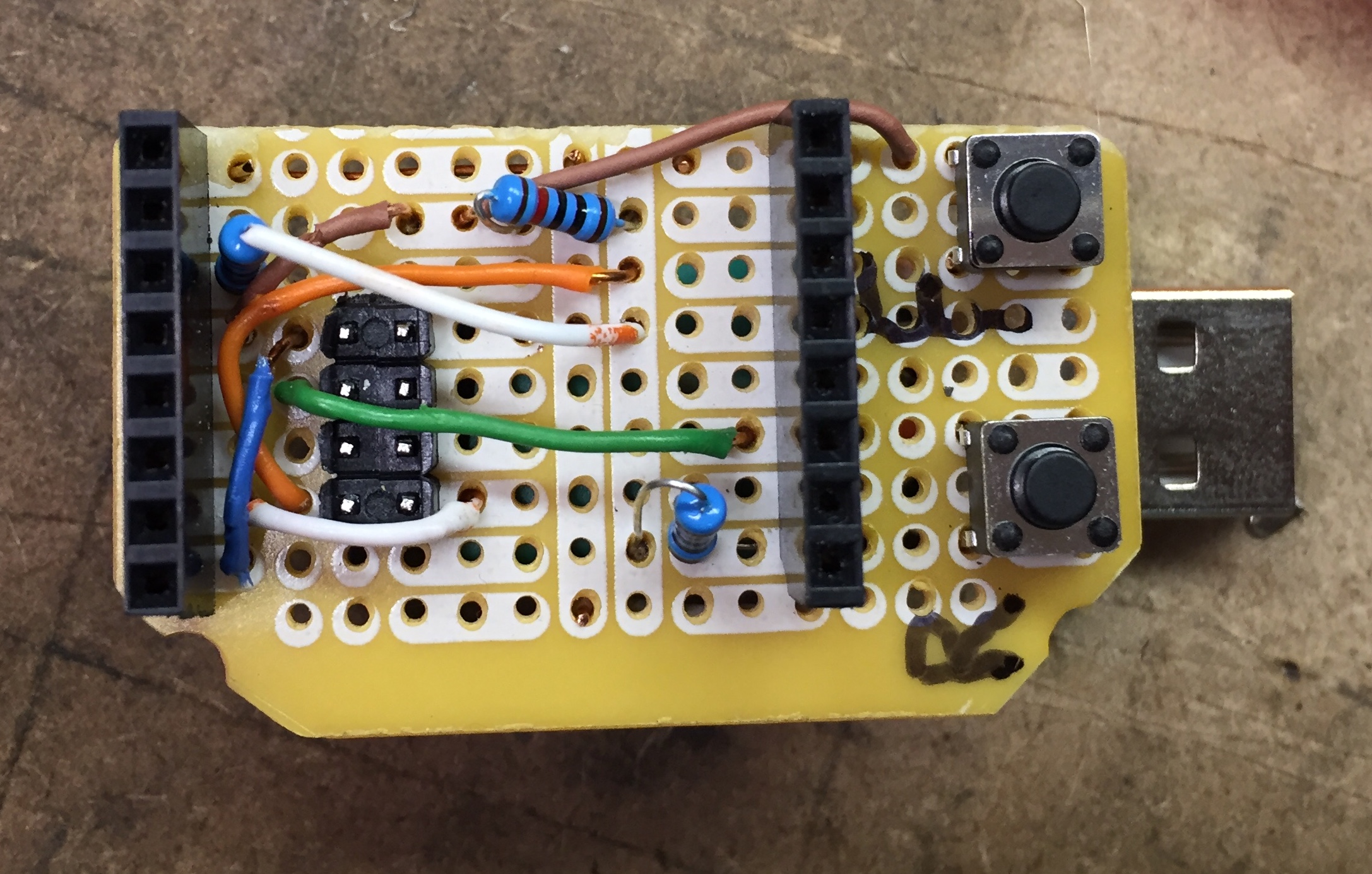
v2 added switches to add in the pull up and pull down 10k resistors to CH_EN and GPIO15 because sometimes I remove them from the bottom of the breakout board and still need to flash it. I also added a little plastic spacer so that the end without the pins rests on the USB connector to make it more stable.
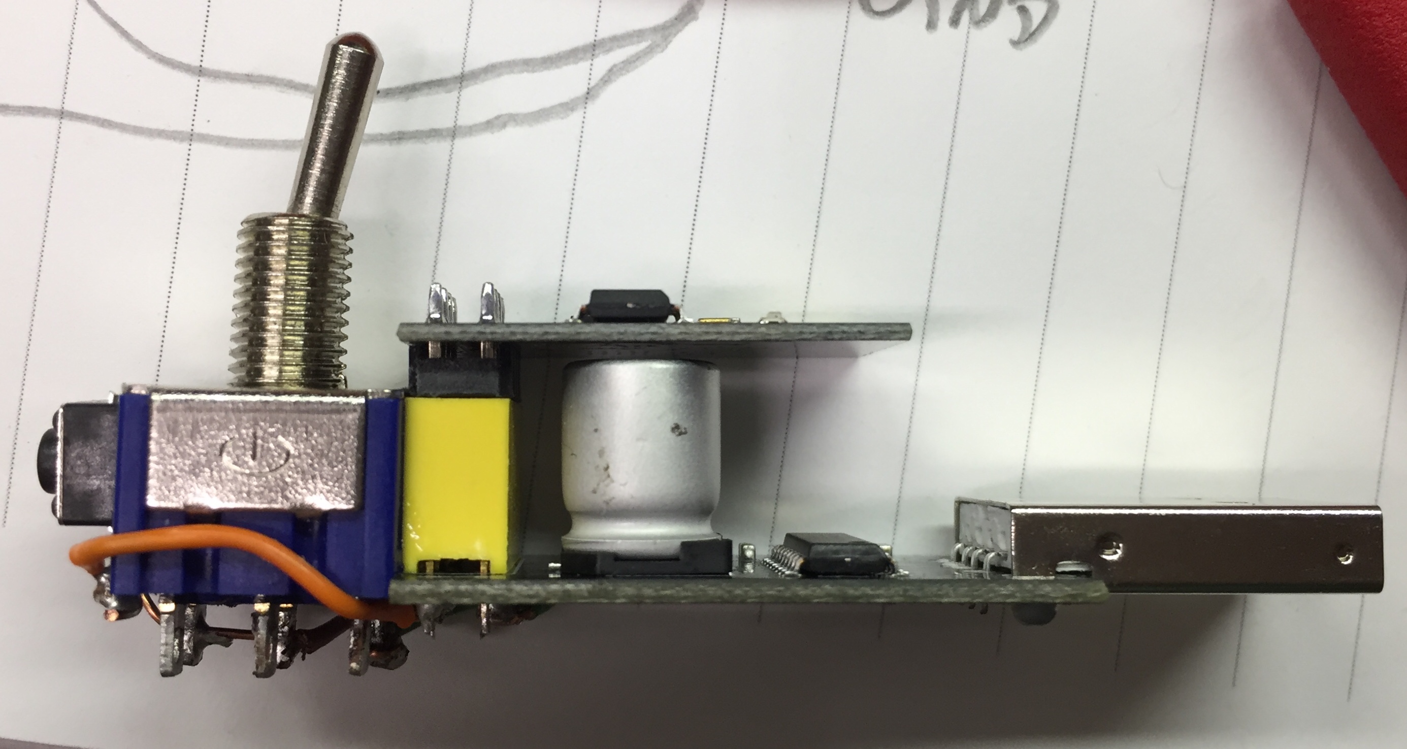
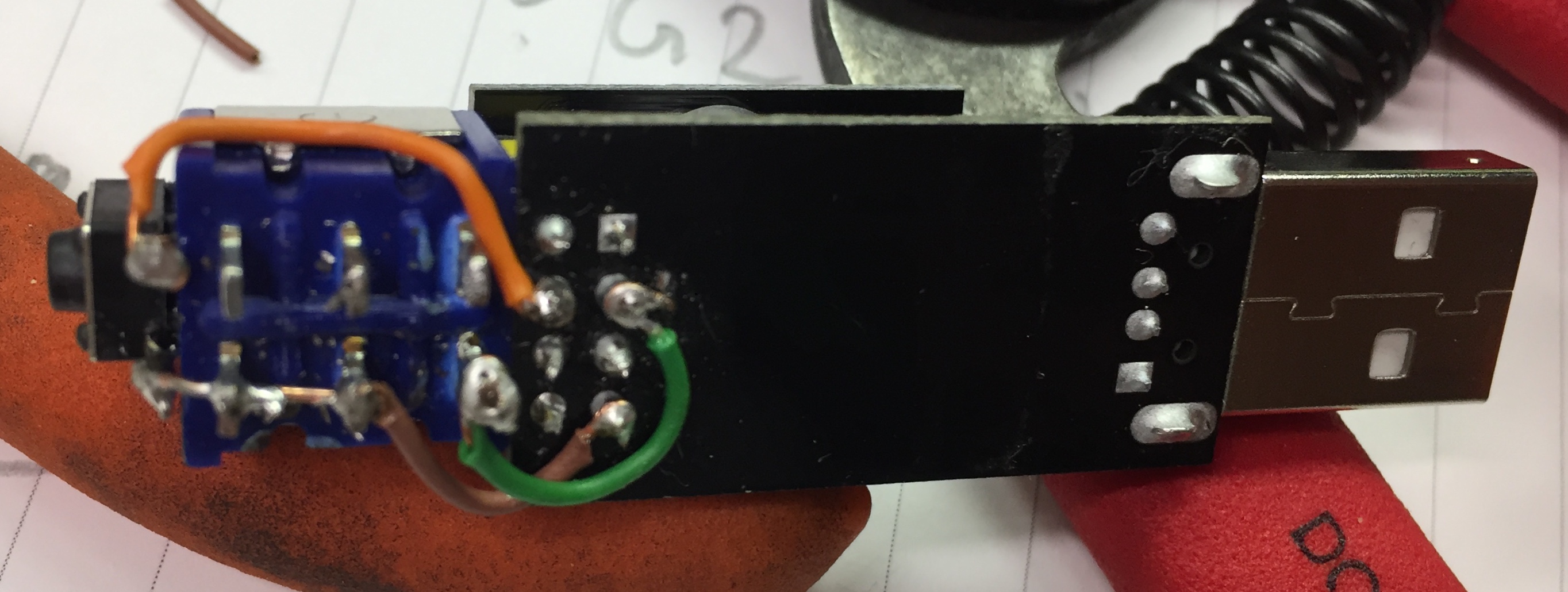
The ease of flashing my boards like this, especially the reset button made me revist my modified ESP01 usb adapter that I made in my first 8266 post. I modified it by super gluing a push button to the end and I got carried away learning all about pull up and pull down resitors that I added those in to where I had just connected the pins directly to ground or VCC in the past. It looked a mess, and didn’t work. I removed all the wiring and wired it up super simple and it worked. I worked out that the USB board already had RST, CH_EN and GPIO2 pulled up so I didn’t need to bother with that so only the switches needed to be connected. It’s much tidier now and the reset button is super helpful.
This post so far makes it sound like everything was going hunky dory. But it wasn’t all hunky or dory most of the time. I had two ESP12 boards that would flash just fine, but show nothing on the terminal expect junk when I reset it. I also had another ESP01 board that would do the same. Firmware that worked on other boards just didn’t work on this one. Finally I worked out that junk on the terminal usually means an incorrect baud rate, so I switched to 115200 rather than 9600 and both ESP12s were working fine, just at a different baud rate. I still have to work out how to fix that but at least they’re not dead.
The ESP01 was more troublesome. none of the selectable baud rates showed anything useful, then I found a bug report that mentioned trying 74880 baud and sure enough then I saw this:
load 0x40100000, len 24976, room 16
tail 0
chksum 0xef
load 0x00000000, len 0, room 8
tail 0
chksum 0xef
load 0x00000000, len 0, room 0
tail 0
chksum 0xef
csum 0xef
csum err
ets_main.c
I’ve got to dig into that and work out what’s up. But since it’s a $1 component I’m not in a huge hurry.
I guess it was a little hunky dory in the long run
Posted Monday 2 December 2019 Share